IviDigitizer Channel Sub-System
The channel sub-system configures the range of voltages the digitizer acquires and how the digitizer couples the input signal to the acquisition sub-system. The main channel sub-system properties include the following:
IviDigitizer Vertical Coupling
All of the channel sub-system properties represent capabilities that are repeated on each of an instrument’s channels. You can set these properties as a group with the IviDigitizer Configure Channel VI.
For each channel, the IviDigitizer Channel Enabled property specifies whether the digitizer acquires a waveform for that channel. You can use this property to disable an unused channel; you may find the property more useful when using the capabilities in extension groups for combining channels (for increased sample rate) or allocating memory (so an unused channel’s memory becomes available to other active channels). For instance, if two channels have been combined into one, one of those channels must be disabled. This property can later be read to determine which channel is active and which is not.
The IviDigitizer Vertical Coupling property specifies how to couple the input signal to the channel sub-system. Most digitizers support AC coupling, which blocks any DC component of the input signal, and DC coupling, which allows the entire signal, including any DC offset, to be sampled.
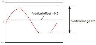
The IviDigitizer Vertical Range property specifies the absolute value of the range of voltages that the digitizer acquires. This range is specified as a peak-to-peak voltage number. The value of the Vertical Offset parameter determines the center of this range.
The IviDigitizer Vertical Offset property specifies the center of the range specified by the Vertical Range property with respect to ground.
You must set these parameters properly before measuring a signal. Digitizers perform best if the input signal is scaled to a range that matches the physical measurement range of the analog-to-digital conversion hardware. Otherwise, clipping of the signal may occur or quantization noise may increase. The following table describes some examples:
| Actual applied signal (sinewave with 1-volt amplitude and 0.2-volt DC offset) | 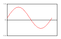 |
| Measured data with: Vertical offset = 0.2 Vertical range = 2 Coupling = DC |
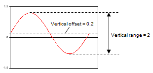 |
| Measured data with: Vertical offset = 0 Vertical range = 2 Coupling = DC |
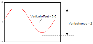 |
| Measured data with: Vertical offset = 0 Vertical range = 2 Coupling = AC |
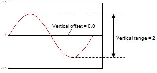 |
| Measured data with: Vertical offset = 0.2 Vertical range = 2 Coupling = AC |
 |